Chapter 10: And, Finally... The Stack
The Stack
The Stack—An Abstract Data Type
Defining characteristic: Last In, First Out (LIFO).
Implementation in Memory
Take the system stack of LC-3 for example. The stack pointer, which keeps track of the top of the stack, is stored in R6. The stack grows from x2FFF (the stack base) to at most x0200.
The code for PUSH and POP operations is as follows. The element to be pushed to or popped from the stack is in R0. If the operation is successful, R5 is 0, otherwise 1.
POP     ST    R2, SaveR2
        ST    R1, SaveR1
        LD    R1, BASE     ; BASE = -x2FFF
        ADD   R1, R1, #-1  ; R1 contains -x4000
        ADD   R2, R6, R1
        BRz   FAIL         ; If stack pointer = x4000, nothing to pop
                           ; This is to prevent an UNDERFLOW.
        LDR   R0, R6, #0   ; The actual POP
        ADD   R6, R6, #1   ; Increment stack pointer
        BRnzp SUCCESS
PUSH    ST    R2, SaveR2
        ST    R1, SaveR1
        LD    R1, MAX      ; MAX = -x0200
        ADD   R2, R6, R1
        BRz   FAIL         ; If stack pointer = x0200, no room for push
                           ; This is to prevent an OVERFLOW.
        ADD   R6, R6, #-1  ; Decrement stack pointer
        STR   R0, R6, #0   ; The actual PUSH
        BRnzp SUCCESS
SUCCESS LD    R1, SaveR1
        LD    R2, SaveR2   ; Restore registers
        AND   R5, R5, #0   ; R5 = 0 indicates success
        RET
FAIL    LD    R1, SaveR1
        LD    R2, SaveR2
        AND   R5, R5, #0
        ADD   R5, R5, #1   ; R5 = 1 indicates failure
        RET
BASE    .FILL xD001        ; BASE = -x2FFF
MAX     .FILL xFE00        ; MAX  = -x0200
SaveR1  .BLKW #1
SaveR2  .BLKW #1
Interrupt-Driven I/O
An I/O device that supports interrupt-driven I/O can:
- Force the current program to stop
- Have the processor carry out the needs of the I/O device, and
- Have the stopped program resume execution as if nothing had happened
Interrupt-driven I/O is useful because it saves a lot of time wasted on polling the I/O devices. The saved time can be used to execute something more useful.
1. Generating the Interrupt Signal
The interrupt signal (INT) stops the current executing process and initiates the interrupt service routine. The INT signal is asserted when:
1) The I/O device wants service.
The Ready bit (bit 15) of the KBSR or the DSR, which is also used in polling, shows if the I/O device wants service.
2) The device has the right to request the service.
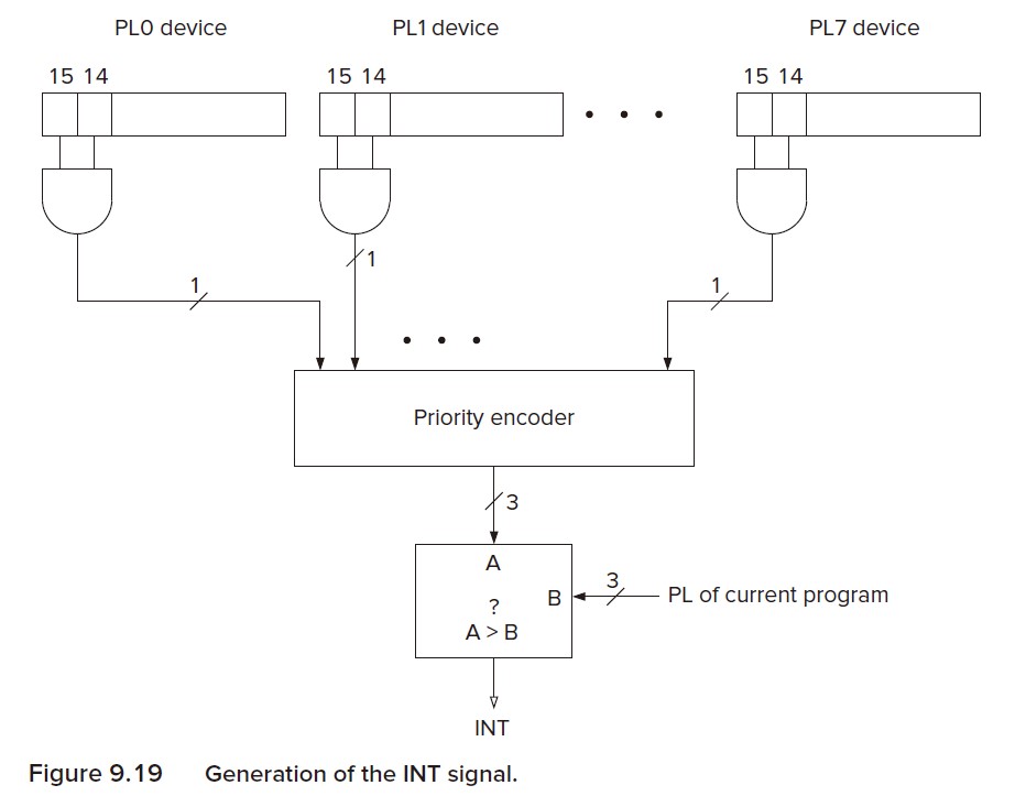
The bit 14 of the KBSR and the DSR are called the interrupt enable bit (IE bit). It can be set or cleared by the processor, depending on whether or not the processor wants to give the I/O device the right to request service.
The interrupt request from the I/O device is the logical AND of the IE bit and the Ready bit.
3) The device request is more urgent than what the processor is currently doing.
The processor does every instruction with a stated level of urgency (priority level, PL). The LC-3 has 8 PLs, from PL0 to PL7. The higher the number, the more urgent the program. The PL of a program is the same as the PL of the request to run that program. That means, the device request must have a higher PL than that of the currently running program.
Any device that has bits 14 and 15 both set asserts its interrupt request signal. The interrupt request signals are input to a priority encoder, which selects the highest priority request, and compares its PL to the PL of the currently executing program. If the PL of that request is higher, the INT signal is asserted.
In LC-3, the PL for I/O interrupts are PL4.
Finally, the INT signal is tested and the interrupt invoked.
The INT signal is tested at state 18, the first state in the instruction cycle. If it is asserted, the processor initiates the interrupt process.
2. Initiate and Service the Interrupt
In order to service the interrupt service and return from it, we need to save 1) enough state info of the currently running program and 2) enough state info of the interrupt service routine.
The State of the Program
The state of the program includes the contents of memory locations that are part of the program, the contents of all the GPRs, the PC and the Process Status Register (PSR). The PSR contains some important information about the status of the currently running program:
| Bits | 15 | 14-11 | 10-8 | 7-3 | 2 | 1 | 0 |
|---|---|---|---|---|---|---|---|
| Contents | Priv | PL | N | Z | P |
PSR[15] indicates whether the program is running under privileged (supervisor) mode (0) or unprivileged (user) mode (1), i.e. whether the program has access to important resources. PSR[10:8] is the PL of the running program. PSR[2:0] is the current condition codes.
Saving the State of the Interrupted Program
When an interrupt takes place, we need to save the contents of the PSR and the PC to the Supervisor Stack.
The Supervisor Stack is used only by programs the execute in privileged mode. On the contrary, the User Stack is used by user programs. R6 is the stack pointer of both stacks. Two internal registers, Saved.SSP and Saved.USP are used to save the stack pointer not in used. When the processor switches from unprivileged to privileged mode, the contents of R6 is saved to Saved.USP and the contents of Saved.SSP is loaded into R6, and vice versa.
To conclude, before the interrupt service routine, R6 is loaded with the contents of Saved.SSP, then the PSR is pushed onto the Supervisor Stack, then the PC.
Loading the State of the Interrupt Service Routine
Next, we should load the PC and PSR of the interrupt service routine.
Interrupt service routines, like TRAP routines, are programs previously stored in memory. Like trap vectors, there are interrupt vectors which indicate the memory locations of the interrupt service routines. In LC-3, the interrupt vector table is saved in memory locations x0100 to x01FF.
The I/O devices that want service will transmit an 8-bit interrupt vector together with its interrupt request signal and PL. The interrupt vector with the highest PL is supplied to the processor. It is designated INTV. Then the processor expands the 8-bit vector to a 16-bit address corresponding to an entry in the interrupt vector table. The processor then loads the PC with the contents of that 16-bit address.
Apart from that, PSR[2:0] is loaded with zeros, PSR[10:8] is set to the priority of the interrupt request, and PSR[15] is loaded with 0, indicating privileged mode.
Service the Interrupt
After all is done, the processors returns to state 18. Since PC is loaded with the starting address of the interrupt service routine, the requirements of the I/O device will be serviced.
Return from the Interrupt
Every interrupt service routine terminates with the instruction RTI. This instruction simply pops the PSR and PC from the supervisor stack, restores them to their rightful places, and R6 is stored to Saved.SSP and loaded with Saved.USP if the processor returns to user mode.
Finally, the processor returns to state 18 and starts executing the next instruction of the caller program as if nothing had happened.